jmathanim
A Java library to make mathematical animations
Project maintained by davidgutierrezrubio Hosted on GitHub Pages — Theme by mattgraham
Transforming Objects
All classes that inherit from MathObject can be transformed. Several methods for shifting, rotating, scaling, or aligning are defined, and most of them have an animated version. Note that most of these methods return the object self, so that they can be applied consecutively like this object.method1().method2()….
Positioning objects
Shift
The shift command shifts the object by the specified vector
Shape c=Shape.circle().shift(Vec.to(1,1));//An unit circle, centered at (1,1)
A simpler 2D-version is also provided:
Shape sq=Shape.square().shift(-3,0);//An unit square, lower left vertex at (-3,0)
MoveTo
The moveTo command shifts the object so that its center is positioned at the given coordinates. Note that the center is the center of the bounding box of the object, not the geometrical center. For regular polygons, for example, they don’t necessarily match.
Shape r=Shape.regularPolygon(5).moveTo(3,3);//A pentagon, with its bounding box centered at (3,3)
Stack()
The stack() command allows us to position an object relative to another one. For example, the following code creates 4 circles and stacks them into a square in different ways:
Shape c1 = Shape.circle().fillColor("orange").fillAlpha(.3);
Shape c2 = c1.copy().fillColor("violet").fillAlpha(.6);
Shape c3 = c1.copy().fillColor("darkgreen").fillAlpha(.5);
Shape c4 = c1.copy().fillColor("darkblue").fillAlpha(.5);
Shape sq = Shape.square().fillColor("darkred").fillAlpha(.3);

c1.stack()//Stack this object...
    .withGaps(.1)//with a gap of .1 units...
    .withDestinyAnchor(AnchorType.LEFT) //to the left of...
    .toObject(sq);//the square sq

c2.stack()//Stack this object...
    .withGaps(.1)//with a gap of .1 units...
    .withDestinyAnchor(AnchorType.RIGHT)//to the right of...
    .toObject(sq);//the square sq

c3.stack()//Stack this object...
    .withDestinyAnchor(AnchorType.UPPER)//to the upper side of...
    .toObject(sq);//the square sq

c4.stack()//Stack using default parameters (center-to-center) to...
    .toObject(sq);//the square sq

add(c1, c2, c3, c4, sq);//Add everything to the scene
camera.adjustToAllObjects(); //Adjust camera, so that everyone gets into the photo
waitSeconds(5);//That is, smile for the screenshot!
which produces the following image:
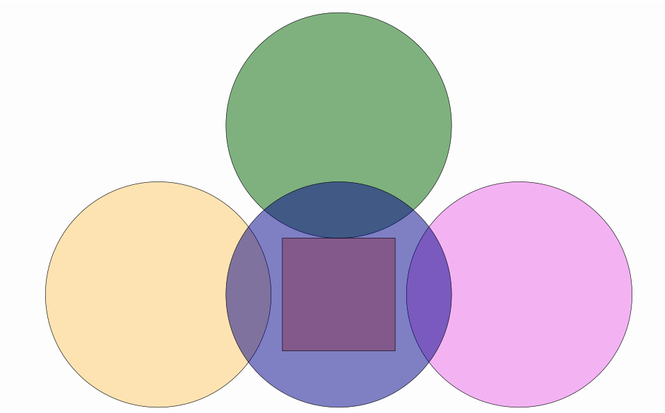
As you can see, the stack() command returns an instance of StackUtils class that allows concatenating additional parameters, so if you want to stack an object, the chain of method should be something like.
myObject.stack()
    <stack parameters, like .withOriginAnchor or .withGaps>
    <command to finish and apply the stack, currrently .toPoint, .toObject or .toScreen>
These are the allowed methods to define how do you want to stack something to something:
.stack() //Start the stacking sequence

.withOriginAnchor(AnchorType anchorOrigin) //Specifies origin anchor (LEFT, RIGHT, etc.). If not defined, reverse destiny anchor will be used (LEFT-RIGHT,etc.)
.withDestinyAnchor(AnchorType anchorDestiny) //Specifies destiny anchor (LEFT, RIGHT, etc.). If not defined, CENTER anchor will be used

.withGaps(double hGap, double vGap) //Specifies horizontal and vertical gaps to apply when stacking the object
.withGaps(double gap) //Overloaded method, equivalent to withGaps(gap,gap)
.withRelativeGaps(double hGap, double vGap) //Similar to the previous method, but gaps are scaled according to the width and height of the origin object (here, widht and height are referred to that of its bounding box).
.withRelativeGaps(double gap) //Overloaded method, equivalent to withRelativeGaps(gap,gap)

//These methods apply the stacking and return the origin object:
.toPoint(Coordinates<?> coords) //Applies the stacking taking destiny as the given coordinates, and returns the origin object
.toObject(Boxable boxable) //Applies the stacking taking destiny as given object and returns the origin object. The destiny can be a MathObject or a Rect object.
.toScreen(ScreenAnchor anchor)//Applies the stacking taking destiny as camera view, using the given screenAnchor object. Any previous withDestinyAnchor method is ignored.
Also, you’ll notice two new methods here: The copy() method returns a copy of the object, and the camera.adjustToAllObjects() does as it says, rescales the camera so that everything fits into view, but it doesn’t zoom in. The fillColor and fillAlpha sets the filling of the object.
Note that the .moveTo(p)method is equivalent to .stack().toPoint(p)
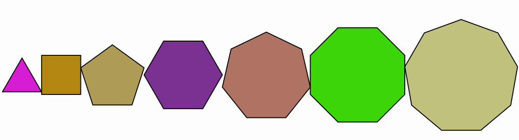
With the stack() command you can easily generate aligned objects:
Shape previousPol = Shape.regularPolygon(3)
    .fillColor("random")
    .thickness(20);//First polygon, with random fill color
add(previousPol);
for (int n = 4; n < 10; n++) {
    Shape pol = Shape.regularPolygon(n)
        .setHeight(previousPol.getHeight())//Scale to have same height as previousPol
        .fillColor("random")//Random fill color
        .thickness(20)
        .stack() //Stack this object...
        .withDestinyAnchor(AnchorType.RIGHT)//to the RIGHT anchor of..
        .toObject(previousPol);//the object previouspol
    add(pol);
    previousPol = pol;//New polygon becomes previous in the next iteration
}
camera.adjustToAllObjects();//Everyone should appear in the photo
waitSeconds(5);//Time for screenshot, but you already should know that
Which produces this regular polygons pattern. Note that all polygons are vertically aligned and their bounding boxes are stacked horizontally. Actually, you can achieve the same effect easier using layouts with MathObjectGroup as we will see later in this chapter.
You can change the Anchor to other values to see how these anchors work. Apart from UPPER, LOWER, LEFT, RIGHT and CENTER there are also RIGHT_AND_ALIGNED_LOWER, RIGHT_AND_ALIGNED_UPPER, LEFT_AND_ALIGNED_UPPER, etc.
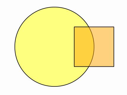
By default, the stack() method takes the appropriate origin anchor point to align with the destination anchor point. For example, .stack().withDestinyAnchor(AnchorType.RIGHT).toObject(obj), as no origin anchor is set, will move the object so that its LEFT anchor (the reverse of RIGHT) matches the RIGHT anchor of the destination object. You can specify the origin and destiny anchors too. For example, this code will place a square so that its center matches the right side of a circle:
Shape sq = Shape.square().scale(.5, .5).fillColor("orange").fillAlpha(.5).thickness(8);
Shape c = Shape.circle().scale(.5).fillColor("firebrick").fillAlpha(.5).thickness(8);
add(c, sq);
sq.stack()
    .withOriginAnchor(AnchorType.CENTER) //Center of the square sq...
    .withDestinyAnchor(AnchorType.RIGHT) //goes to the right of...
    .toObject(c); //the circle c
waitSeconds(3);
Stack to screen
This methods is similar to stack().toObject(), but it positions the object relative to the current view.
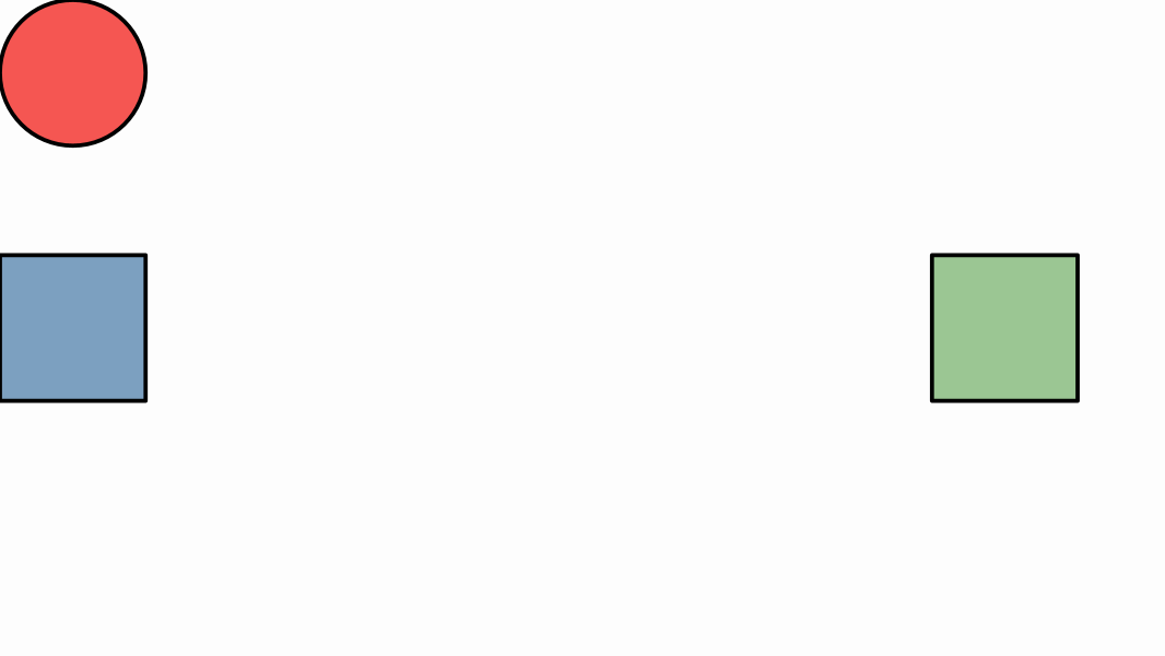
Shape square1 = Shape.square().scale(.5).style("solidblue");
Shape square2 = Shape.square().scale(.5).style("solidgreen");
Shape circle1 = Shape.circle().style("solidred").scale(.25);
Shape circle2 = Shape.circle().style("solidorange").scale(.25);

square1.stack()//Stack this object...
    .toScreen(ScreenAnchor.LEFT);//to the left of the screen, with no gaps

square2.stack() //Stack this object...
    .withGaps(.3)//with gaps .3...
    .toScreen(ScreenAnchor.RIGHT);//to the right of the screen

circle1.stack()//Stack this object...
    .withOriginAnchor(AnchorType.CENTER)//so that its center...
    .toScreen(ScreenAnchor.UPPER_LEFT);//matchs the upper left corner of the screen

circle2.stack()//Stack this object...
    .withOriginAnchor(AnchorType.LOWER)//so that its lower anchor...
    .toScreen(ScreenAnchor.LOWER_RIGHT);//matchs the lower right corner of the screen

//Add everything to the scene
add(square1, square2, circle1,circle2);
waitSeconds(5);
You obtain objects stacked to the borders of the actual screen view:
There is shortcut method if you want to simply put the object at the center of the screen. The method .center() is equivalent to .stack().toScreen(ScreenAnchor.CENTER).
Aligning objects
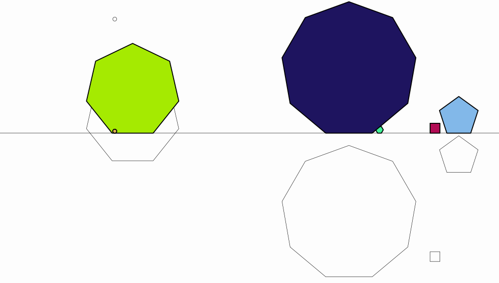
The MathObjectclass has the method align which aligns the object with another one, using one of the aligns in the enum AlignType: LEFT, RIGHT, UPPER, LOWER, HCENTER, VCENTER.
Line floor = Line.XAxis();
add(floor);
for (int n = 4; n < 10; n++) {
    Shape pol = Shape.regularPolygon(n) //Creates a regular polygon with n sides...
        .moveTo(Point.random()) //Move its center to a random point on current view...
        .scale(Math.random() * .5);//And scale it randomly between 0 and 0.5
    Shape pol2 = pol.copy() //Creates a copy of the polygon...
        .fillColor("random") //fill it with a random color...
        .thickness(6) //With this thickness...
        .align(floor, AlignType.LOWER);//And align the bottom of the object with object floor
    add(pol, pol2);
}
camera.adjustToAllObjects();//Everyone should appear in the photo
waitSeconds(5);//Smile!
Scaling objects
All MathObject instances can be scaled with the scale command. Scaling can be done from a given scale center or by default, the center of the object bounding box.
@Override
public void setupSketch() {
    config.parseFile("#preview.xml");
    config.parseFile("#light.xml");
}

@Override
public void runSketch() throws Exception {
    Shape s1=Shape.circle()//A circle...
        .style("solidorange")//Style solidorange (included in #light.xml)
        .shift(-1, 0) //Shifted 1 unit to the left
        .scale(.5, 1);//x-scale and y-scale around center
    Shape s2=Shape.regularPolygon(5)//A regular pentagon...
        .style("solidred")//Style solidred (included in #light.xml)
        .shift(0, 1)//Shifted 1 unit up
        .scale(Point.at(0, 0), 1.3, .2);//x-scale and y-scale around (0,0)
    Shape s3=Shape.square() //A square...
        .style("solidblue")//Style solidblue (included in #light.xml)
        .shift(1, 0)//shifted 1 unit to the left
        .scale(.3); //Uniform scale around center
    add(s1,s2,s3);
    waitSeconds(5);
}
produces the result:
Rotating objects
The rotate command rotates the object around a given center (or the center of the object if none is given). The angle is specified in radians but can also be given in degrees using the DEGREES constant. The format is object.rotate(center_of_rotation,angle) or object.rotate(angle). As in the scale method, if no center is specified, the center of the bounding box is chosen as rotation center.
For example:
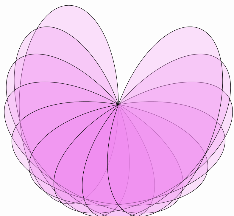
Shape ellipse = Shape.circle().scale(.5, 1);//Creates an ellipse
ellipse.fillColor("violet").fillAlpha(.25);//fill violet 25% opacity
Point rotationCenter = Point.at(.5, 0);
for (int n = 0; n < 180; n += 20) {
    add(ellipse.copy().rotate(rotationCenter, n * DEGREES));
}
waitSeconds(5);
Gives this spirograh-like picture:
Affine Transforms
shift, rotate and scale are particular cases of a more general affine transform implemented by the AffineJTransform class. This class defines general affine transforms in the 2D plane, and has several static convenience methods for some of the most common transforms:
The createTranslationTransform(Vec v) or createTranslationTransform(Point A, Point B) creates a translation transform. The shift command is just a shortcut for this transform.
The create2DRotationTransform(Point center, double angle) creates a rotation transform, which is used in the rotate command.
The createScaleTransform(Point center, double sx, double sy, double sz) creates a scaling transform. The z-scale factor is here for
compatibility to extend to the 3D case, but is currently not used. Used in the scale command.
Given any MathObject instance, there are 2 main methods to use an AffineJTransform object on it:
-
The
transform.applyTransform(object)method transforms and modifies the current object, returningvoid. -
The
transform.getTransformed(object)returns a copy of the object transformed. The original object is unaltered.
Isomorphic transformations
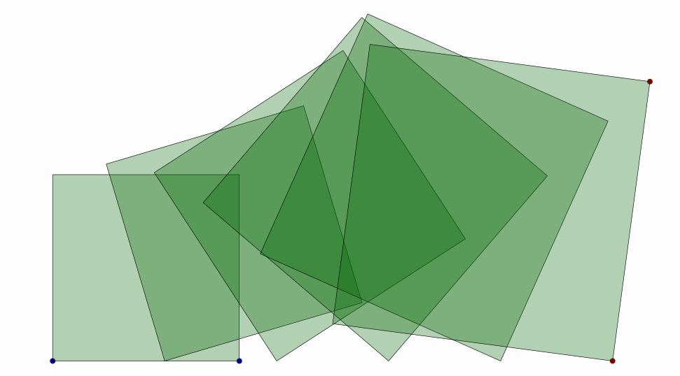
The createDirect2DIsomorphic(Point A, Point B, Point C, Point D, double alpha) is a combination of shifting, rotating and uniform scaling. This method generates the (only) direct transform of this type that maps the points (A,B) into points (C,D). The alpha parameter is used for animations, as a value of alpha=0 returns the identity transform and alpha=1 returns the full transform. Intermediate values return intermediate transforms, interpolating the shifting, rotating, and scaling parameters adequately. These transforms preserve not the size, but the shape and proportions of the objects.
Look at the following example:
Shape sq = Shape.square()
    .shift(-1.5, -1)
    .fillColor("darkgreen")
    .fillAlpha(.3);//Square, fill color dark green, and opacity 30%
Point A = sq.getPoint(0)
    .drawColor("darkblue");//First vertex of the square (lower-left corner), dark blue color
Point B = sq.getPoint(1)
    .drawColor("darkblue");//First vertex of the square (lower-right corner), dark blue color
Point C = Point.at(1.5, -1)
    .drawColor("darkred");//Destiny point of A, dark red color
Point D = Point.at(1.7, .5)
    .drawColor("darkred");//Destiny point of B, dark red color

add(A, B, C, D);
for (double alpha = 0; alpha <= 1; alpha += .2) {
    AffineJTransform transform = AffineJTransform.createDirect2DIsomorphic(A, B, C, D, alpha);
    add(transform.getTransformedObject(sq));//Adds a copy of the square, transformed
}
waitSeconds(5);
Produces the following sequence of interpolated transforms from one square to another. Note that this transformation may change the scale of objects, but proportions are unaltered:
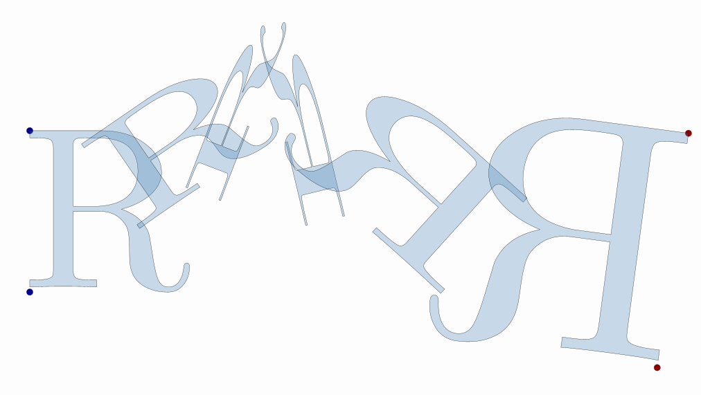
Since version 0.9.9-SNAPSHOT, the createInverse2DIsomorphic method is implemented too, that returns the (only) inverse isomorphic transform that maps A into C and B into D.
//Generates a LatexMathObject and gets the first shape, fill it with color steelblue, and opacity 30%
LatexShape bigR = LatexMathObject.make("R").get(0).scale(8).center().fillColor("steelblue").fillAlpha(.3);

//Create a point located at the lower left corner of the bounding box of bigR
Point A = Point.at(bigR.getBoundingBox().getLowerLeft())
    .drawColor("darkblue");

//Create a point located at the upper left corner of the bounding box of bigR
Point B = Point.at(bigR.getBoundingBox().getUpperLeft())
    .drawColor("darkblue");

Point C = Point.at(3.5, -1).drawColor("darkred");//Destiny point of A, dark red color
Point D = Point.at(3.7, .5).drawColor("darkred");//Destiny point of B, dark red color

add(A, B, C, D);
for (double alpha = 0; alpha <= 1; alpha += .2) {
    //Inverse isomorphic transformation that maps (A,B) onto (C,D)
    AffineJTransform transform = AffineJTransform.createInverse2DIsomorphic(A, B,
                                                                            C, D,
                                                                            alpha);
    add(transform.getTransformedObject(bigR));//Adds a copy of the square, transformed
}
camera.adjustToAllObjects();
waitSeconds(5);
Reflections
If we want to make a reflection of an object, we can use the static methods createReflection and createReflectionByAxis. They differ in the way the transformation is specified:
-
createReflection(Point A, Point B, double alpha)creates the (only) reflection that maps pointAinto pointB. The reflection axis is the perpendicular bisector of the segment joining the two points. -
createReflectionByAxis(Point E1, Point E2, double alpha)creates the (only) reflection with axis the line specified by the pointsE1andE2.
In both cases, the alpha parameter works in a similar way to the isomorphic transform.
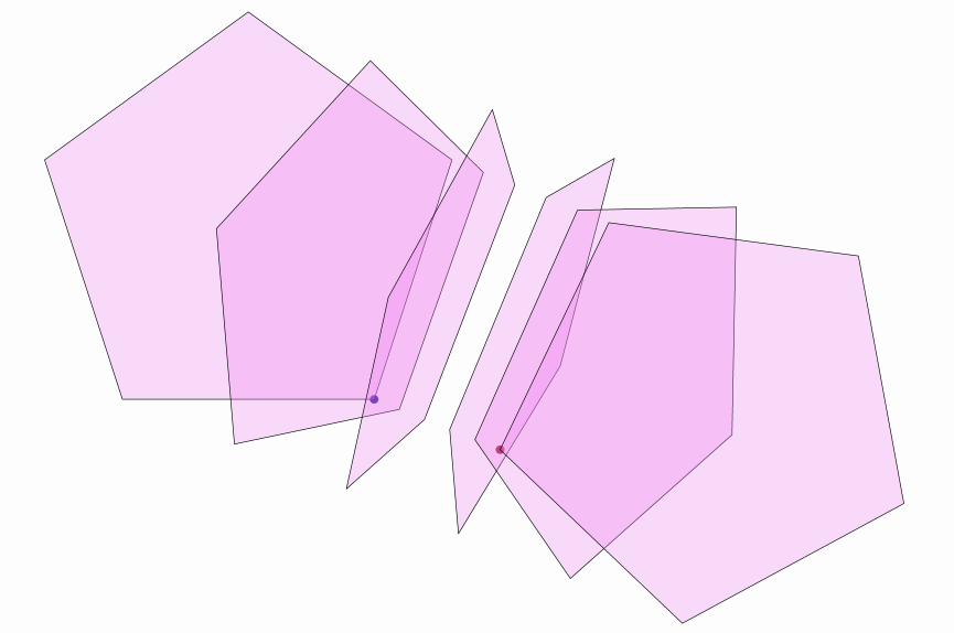
An example of createReflection is shown in the following source code:
Shape sq = Shape.regularPolygon(5).fillColor("violet").fillAlpha(.3);//Regular pentagon, fill violet, opacity 30%
Point A = sq.getPoint(0).copy().drawColor("darkblue");//Copy of the first vertex of the pentagon(lower-right corner), color dark blue
Point B = A.copy().shift(.5, -.2).drawColor("darkred");//Copy of A, shifted (.5,-2), color dark red
add(A, B);
for (double alpha = 0; alpha <= 1; alpha += .2) {
    AffineJTransform transform = AffineJTransform.createReflection(A, B, alpha);//Reflection that maps A into B
    add(transform.getTransformedObject(sq));//Adds a copy of the pentagon, transformed
}
camera.adjustToAllObjects();
waitSeconds(5);
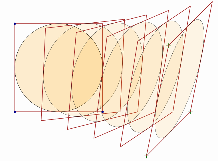
General affine transforms
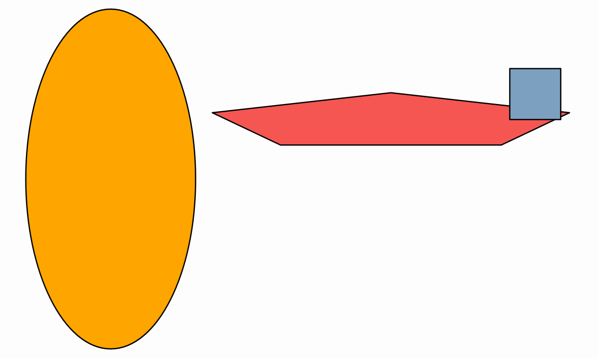
There is also a more general way to define an affine transform using createAffineTransformation(Point A, Point B, Point C, Point D, Point E, Point F, double lambda). It returns the (only) affine transform that maps the points (A,B,C) into (D,E,F), with the lambda interpolation parameter as in the previous methods. Here’s an example:
Shape sq = Shape.square().drawColor("brown").thickness(4);
Shape circ = Shape.circle().scale(.5).shift(.5, .5).fillColor("orange").fillAlpha(.1);//A circle inscribed into the square
//We create the points with layer(1) so that the draw over the square and circles (by default in layer 0)
Point A = Point.at(0, 0).drawColor("darkblue").layer(1);
Point B = Point.at(1, 0).drawColor("darkblue").layer(1);
Point C = Point.at(0, 1).drawColor("darkblue").layer(1);
Point D = Point.at(1.5, -.5).dotStyle(DotStyle.PLUS).thickness(6).drawColor("darkgreen");
Point E = Point.at(2, 0).dotStyle(DotStyle.PLUS).thickness(6).drawColor("darkgreen");
Point F = Point.at(1.75, .75).dotStyle(DotStyle.PLUS).thickness(6).drawColor("darkgreen");
add(sq, circ, A, B, C, D, E, F);

for (double alpha = 0; alpha <= 1; alpha += .2) {
    //A maps to D,B maps to E, C maps to F
    AffineJTransform transform = AffineJTransform.createAffineTransformation(A, B, C, D, E, F, alpha);
    add(transform.getTransformedObject(sq));//Adds a copy of the square, transformed
    add(transform.getTransformedObject(circ));//Adds a copy of the circle, transformed
}
camera.adjustToAllObjects();
waitSeconds(5);
That produces the following image:
Layouts
The MathObjectGroupclass allows applying layouts to its members through the setLayout(layout,gap) method, which positions all objects with the given layout and specified gap. The layouts are defined in the enum MathObjectGroup.Layout and currently are CENTER, LEFT, RIGHT, UPPER and LOWER, which aligns the objects centered in these directions. There are also the versions URIGHT, DRIGHT, ULEFT, DLEFT which work in a similar way but align at the top (U) o bottom (D), and LUPPER, RUPPER, LLOWER, RLOWER that align to the left (L) or right (R). There are also the DIAG1, DIAG2, DIAG3, and DIAG4 layouts that align in the main diagonals of the 4 sectors (45, 135, 225 and 315 degrees).
The following code shows all current layouts, with a set of 10 increasing squares:
MathObjectGroup group = MathObjectGroup.make();
double h = 0;//This will hold the total height of the squares, to properly zoom out the camera later
for (int n = 0; n < 10; n++) {
    Shape square = Shape.square().scale(.2 + .1 * n).fillColor("random").fillAlpha(.5).thickness(6);
    h += square.getHeight();
    group.add(square);
}
camera.scale(2 * h / camera.getMathView().getHeight());//Zooms out so that the height of view is 2xTotal height
add(group);//This adds all squares to the scene, but not the group object itself.
LatexMathObject layoutName = LatexMathObject.make("").scale(7);
add(layoutName);
for (LayoutType layout : LayoutType.values()) {//Iterate over all the layout values
    group.setLayout(layout, .1); //Set this layout, with .1 gap between objects
    layoutName.setLaTeX(layout.name())
        .stack()
        .withRelativeGaps(.2)
        .toScreen(ScreenAnchor.LOWER);
    waitSeconds(3);
}
There is a more advanced overloaded form of this method, where the layout is given as a subclass of the GroupLayout class. Since version 0.8.9, the BoxLayout, SpiralLayout, HeapLayout and PascalLayout have been implemented. These methods work well when all elements of the group have the same dimensions. You can define your own layouts subclassing the GroupLayout abstract class.
The BoxLayout
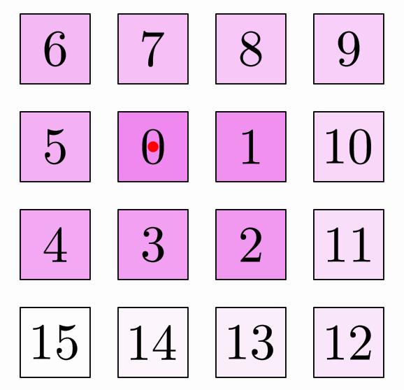
The BoxLayout allocates the objects in a matrix form:
MathObjectGroup gr = MathObjectGroup.make();
int num = 16;
for (int n = 0; n < num; n++) {
    Shape sq = Shape.square().scale(.25).fillColor("violet").fillAlpha(1 - 1. * (n+1) / num).thickness(6);
    LatexMathObject t = LatexMathObject.make("" + n);
    t.stack().toObject(sq).layer(1);
    gr.add(MathObjectGroup.make(sq, t));//Each object of the group is itself a group with 2 elements
}
Point refPoint = Point.origin(); //The reference point to locate the box
add(refPoint.thickness(40).drawColor("red").layer(1));
BoxLayout layout = BoxLayout.make(refPoint, 4,  .1, .1);//This is where the magic happens
add(gr.setLayout(layout));
camera.zoomToAllObjects();
waitSeconds(3);//Smile, you're in a screenshot!
Gives a static image like this. The red dot is the reference point
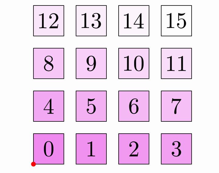
As you can see, the default direction is first fill rows left-to-right and then proceed down-to-up. This corresponds to theBoxDirection.RIGHT_UP enum parameter, that tells the layout to first fill the row in the RIGHT direction, and then go UP to move to the next one. You can try other values, like LEFT_DOWN, for example, with the method setDirection.
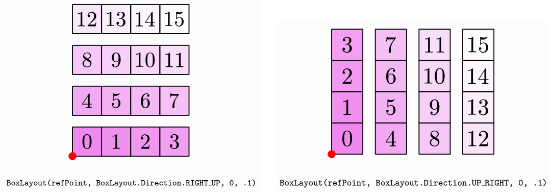
The gaps are not the usual horizontal and vertical gaps, but the in-row-gap, and between-row gaps. The “row” term in this case is not the usual horizontal row, but the lower level groups of objects. For example, if direction is RIGHT_DOWN , RIGHT_UP, LEFT_DOWN or LEFT_UP the “rows” will be horizontal and the in-row-gap will act like a horizontal gap (and the between-rows-gap like a vertical gap), but if direction is UP_RIGHT, UP_LEFT, DOWN_RIGHT, or DOWN_LEFT, the “rows” will be vertical and the in-row-gap will act like a vertical gap. An image is worth a thousand words:
The BoxLayout has the methods getRowGroups and getColumnGroups which return a MathObjectGroup with its elements other MathObjectGroup objects, each one with the elements of a row (or column).
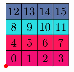
For example, if you add the following lines right before the waitSecondscommand in the previous code, you can assign random fill colors to each row:
for(MathObjectGroup rows:layout.getRowGroups(gr)) {//Iterate over the rows
	rows.fillColor("random");
}
The SpiralLayout
If in the previous code you change the
BoxLayout layout = BoxLayout.make(refPoint, 4, .1, .1);//This is where the magic happens
into
SpiralLayout layout = SpiralLayout.make(refPoint, SpiralLayout.Orientation.RIGHT_CLOCKWISE, .1, .1);//Another kind of magic!
You will get the objects in a spiral form:
The orientation parameter specifies if the spiral is clockwise or counterclockwise and the position of the second object relative to the first one (which is centered at the reference point). The gaps are the usual horizontal and vertical gaps.
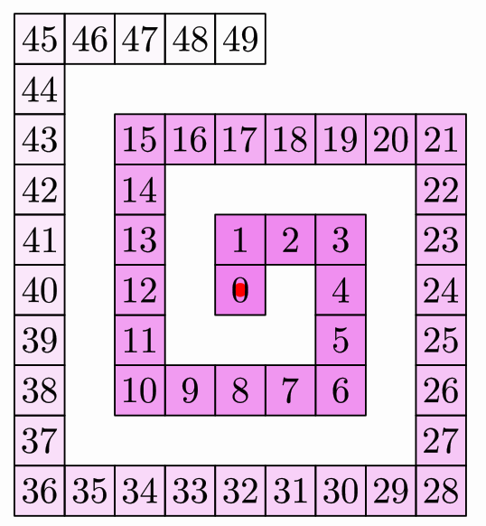
This class has the methodsetSpiralGap that admits an integer parameter that controls the aperture of the spiral. The default value is 0. A value of 1 will leave a single space between consecutive turns of the spiral. A value of 2 will leave 2 spaces, etc. If in the previous example we make the following change in the number of squares and the creation of the layout:
int num=50;//Now we are creating more squares!
........
SpiralLayout layout = SpiralLayout.make(refPoint, SpiralLayout.Orientation.RIGHT_CLOCKWISE, 0, 0).setSpiralGap(1);
You will obtain the following image:
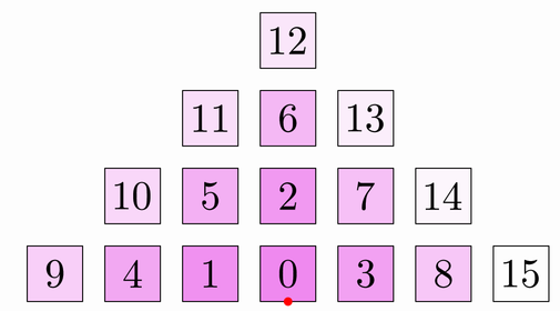
The HeapLayout
If you use the HeapLayout:
HeapLayout layout = HeapLayout.make(refPoint, .1, .1);
You will get a triangular pile of numbered squares:
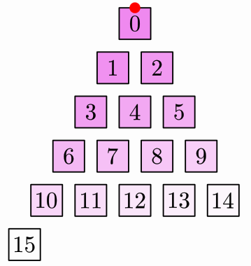
The PascalLayout
The PascalLayout resembles the positions of numbers in the Pascal triangle. If you use the code:
PascalLayout layout = PascalLayout.make(refPoint,.1,.1);
You will obtain a layout like this:
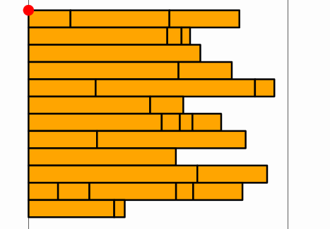
The FlowLayout
The FlowLayout is similar to the BoxLayout except the new row is created when exceeds certain width, most like a text editor will do.
int num = 70;
MathObjectGroup sqs = MathObjectGroup.make();
for (int n = 0; n < num; n++) {//Create random bars
    sqs.add(
        Shape.square().scale(Math.random(), .1).fillColor("random")
    );
}
double width = 4;
final Point corner = Point.relAt(.1, .9);
add(corner.thickness(40).drawColor("red").layer(1));
add(Line.YAxis().shift(corner.v.add(Vec.to(width, 0))));//Draw vertical lines to mark the margins
add(Line.YAxis().shift(corner.v.add(Vec.to(0, 0))));
FlowLayout flayout = FlowLayout.make(corner, width, .1,.1);
   .setDirection(BoxDirection.RIGHT_DOWN);
sqs.setLayout(flayout);
add(sqs);
camera.adjustToObjects(sqs);
waitSeconds(2);
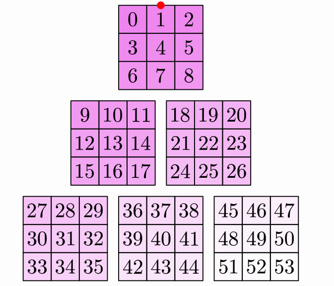
Composing layouts
From version 0.9.2-SNAPSHOT the ComposeLayout allows the creation of more complex layouts by composition. The syntax for creating a composite layout is
ComposeLayout composedLayout=ComposeLayout.make(outerLayout, innerLayout, size);
When applied to a group, this layout will first divide the group into subgroups of size elements, then will layout each one with the inner layout, and finally it will layout each subgroup, as an individual object, with the outer layout.
We illustrate this with an example. Here we use as inner layout a BoxLayout and as outer layout a PascalLayout.
MathObjectGroup gr = MathObjectGroup.make();
int num = 54;
for (int n = 0; n < num; n++) {//Creates a group with 54 numbered squares
    Shape sq = Shape.square().scale(.25).fillColor("violet").fillAlpha(1 - 1. * (n + 1) / num).thickness(6);
    LatexMathObject t = LatexMathObject.make("" + n);
    t.stack().toObject(sq).layer(1);
    gr.add(MathObjectGroup.make(sq, t));//Each object of the group is itself a group with 2 elements
}

Point refPoint = Point.origin(); //The reference point to locate the outer layout
add(refPoint.thickness(40).drawColor("red").layer(1));//add this point so we can see it clearly

GroupLayout innerLayout = BoxLayout.make(refPoint, 3, 0, 0)
    .setDirection(BoxDirection.RIGHT_DOWN);
GroupLayout outerLayout = PascalLayout.make(refPoint, .1, .1);
ComposeLayout composedLayout = ComposeLayout.make(outerLayout, innerLayout, 9);//The composed layout

add(gr.setLayout(composedLayout));
camera.adjustToAllObjects();
waitSeconds(3);//Smile, you're in a screenshot!
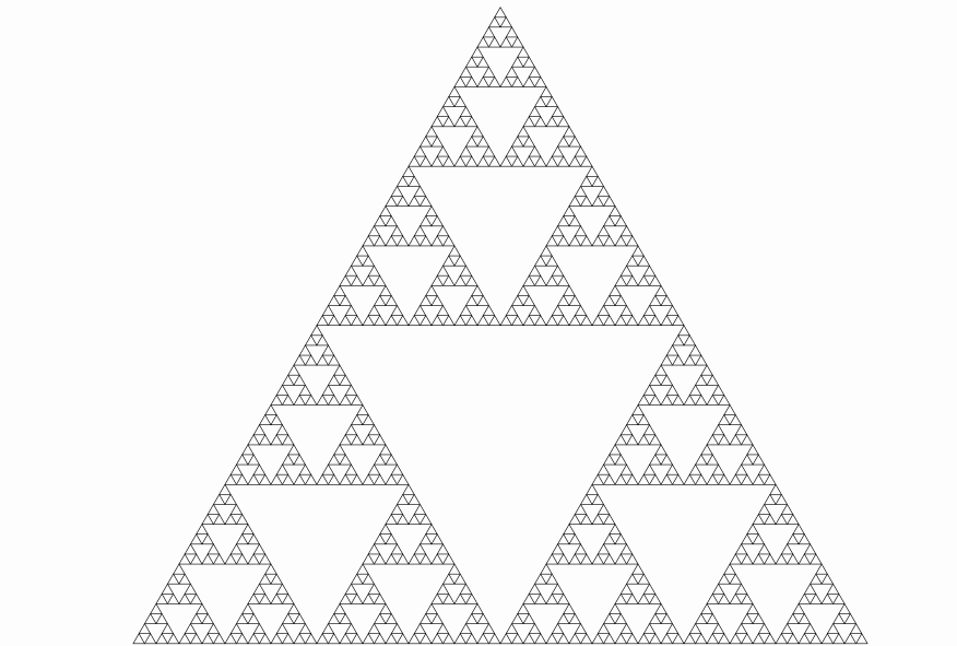
Another example: we use composite layouts to draw a Sierpinski triangle using a group of equilateral triangles and iterating compositions:
int degree = 6;//Degree of the Sierpinski triangle
int num = (int) Math.pow(3, degree);//We need 3^degree triangles!
Shape tr = Shape.regularPolygon(3).scale(.25);//Base triangle

//This method creates a group with num copies of the same object
MathObjectGroup triangles = MathObjectGroup.makeCopies(tr, num);

Vec corner = Vec.to(0,0);//Coordinates of top corner of the Sierpinski triangle
PascalLayout innerLayout = PascalLayout.make(corner, 0, 0);

GroupLayout previousLayout = innerLayout;
GroupLayout sierpinskiLayout = innerLayout;
for (int n = 1; n < degree; n++) {//Iterates composing the innerLayout with itself 6 times
    sierpinskiLayout = ComposeLayout.make(previousLayout, innerLayout, 3);
    previousLayout = sierpinskiLayout;
}
sierpinskiLayout.applyLayout(triangles);
add(triangles);
camera.adjustToAllObjects();
waitSeconds(5);
We obtain the following image (note that there are 729 triangles in there):